Cookbook
Three end-to-end recipes that combine everything from the previous chapters. Each one is a standalone script you can run as python <name>.py.
Mach-Zehnder interferometer
An MZI: Y-splitter, two arms of different geometry, Y-combiner. The top arm carries a chained taper pair (a phase-shifter region); the bottom arm jogs south for a delay.
"""Cookbook: a Mach-Zehnder interferometer.

Two paths between a Y-splitter and a Y-combiner. The top arm carries a
chained taper pair (a thermal phase shifter region); the bottom arm
takes a delay via .jog(). This example does not request length matching.
"""
import lumicron as lm
import lumicron.pdks.elyon_demo.all as pdk


@lm.pcell
def YSplitter(width: float = 0.5):
    """Stand-in Y-junction with three ports: i1, o1, o2."""
    c = lm.CELL("YSplitter")
    body = lm.Rectangle(x_dim=20, y_dim=4, layer=pdk.LAYER.SILC)
    c.add(body)
    c.Place(body).at((0, 0))
    c.add(lm.PORT("i1", position=(0, 0), direction=180,
                  width=width, route_profile=pdk.RP.silc_strip))
    c.add(lm.PORT("o1", position=(20, 1.5), direction=0,
                  width=width, route_profile=pdk.RP.silc_strip))
    c.add(lm.PORT("o2", position=(20, -1.5), direction=0,
                  width=width, route_profile=pdk.RP.silc_strip))
    return c


@lm.pcell
def MZI(arm_length: float = 400, delay: float = 60):
    c = lm.CELL("MZI")

    s = c.add(YSplitter())
    k = c.add(YSplitter())

    c.Place(s).at((0, 0))
    c.Place(k).at((arm_length + 60, 0)).rotate_by(180)

    # Top arm — straight, with a phase-shifter taper bay.
    (c.Route(s.ports["o1"], radius=15, bend="euler").to(k.ports["o2"])
        .taper(offset=120, width=2.0, length=20)
        .taper(offset=120, width=0.5, length=20))

    # Bottom arm — jog south by `delay` to add a delay region.
    c.Route(s.ports["o2"], radius=15, bend="euler").to(k.ports["o1"]) \
        .jog("S", by=delay)
    return c


if __name__ == "__main__":
    MZI().to_gds("mzi.gds")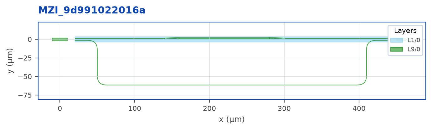
What to notice:
@lm.pcellturnsYSplitterinto a parametrized cell factory. Two calls with the same parameters share the same cell definition under the hood; only the references differ.- Combiner is rotated 180° so its
o1ando2face left toward the splitter’s arm ports. .taper(...)is chained twice to widen, hold, and narrow the top arm. Width carries forward between chained tapers..jog("S", by=delay)on the bottom arm is the entire delay region - no manual segments.
This example does not request length matching or establish equal arm lengths. For an explicit ΔL, retain the route handles and use the length-matching workflow in the Routing chapter.
Ring resonator
A single-bus, single-ring add/drop. The ring is just a lm.Ring shape; its position is determined by radius + width/2 + gap from the bus center.
"""Cookbook: a single-bus ring resonator.

A bus waveguide running east-west, a ring sitting above it with the
gap controlled by `gap`. The ring is just a `lm.Ring` shape on the same
layer as the bus.
"""
import lumicron as lm
import lumicron.pdks.elyon_demo.all as pdk


@lm.pcell
def RingResonator(
    radius: float = 25,
    width: float = 0.5,
    gap: float = 0.2,
    bus_length: float = 200,
):
    c = lm.CELL("RingResonator")

    # Bus waveguide: a flat rectangle along the silicon strip layer.
    bus = lm.Rectangle(x_dim=bus_length, y_dim=width, layer=pdk.LAYER.SILC)
    c.add(bus)
    c.Place(bus).at((0, 0))

    # Ring centered above the bus, separated by gap.
    ring_y = width / 2 + gap + radius
    ring = lm.Ring(outer_radius=radius, width=width, layer=pdk.LAYER.SILC)
    c.add(ring)
    c.Place(ring).at((bus_length / 2, ring_y))

    c.add(lm.PORT("in", position=(0, 0), direction=180,
                  width=width, layer=pdk.LAYER.SILC))
    c.add(lm.PORT("out", position=(bus_length, 0), direction=0,
                  width=width, layer=pdk.LAYER.SILC))
    return c


if __name__ == "__main__":
    RingResonator().to_gds("ring_resonator.gds")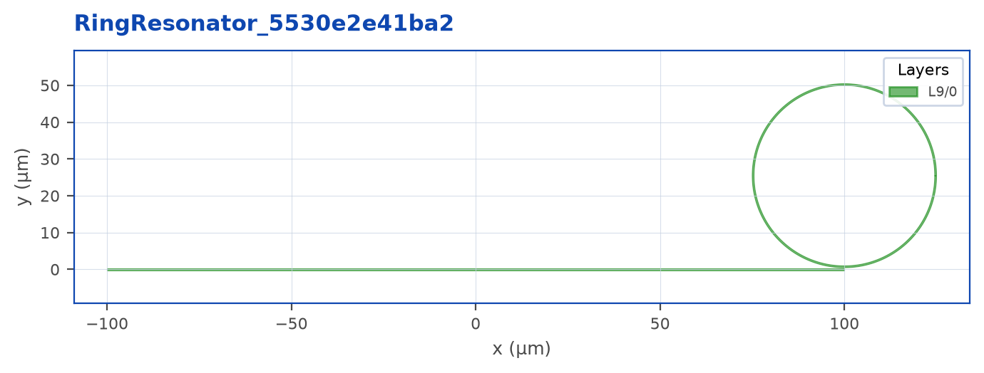
For an add/drop (two-bus) ring, add a second Rectangle on the opposite side of the ring at the same gap and a second pair of ports. To sweep radius or coupling gap across a die, wrap this in @lm.pcell(radius=..., gap=...) and place the array.
Fanout bus
Four channels entering at 10 µm pitch, leaving at 50 µm. The bundle absorbs the pitch difference with auto-fanouts - no manual U-detours.
"""Cookbook: a tight bundle fanned out to a wider port pitch.

A 4-channel bundle entering at 10 µm pitch and leaving at 50 µm. The
auto-fanout absorbs the pitch difference into a U-shape on each side;
the spine in between stays parallel and tight.
"""
import lumicron as lm
import lumicron.pdks.elyon_demo.all as pdk


@lm.pcell
def FanoutBus(
    n: int = 4,
    pitch_in: float = 10.0,
    pitch_out: float = 50.0,
    span: float = 600.0,
):
    c = lm.CELL("FanoutBus")

    for i in range(n):
        c.add(lm.PORT(
            f"in{i}", position=(0, i * pitch_in), direction=0,
            route_profile=pdk.RP.silc_strip,
        ))
        c.add(lm.PORT(
            f"out{i}", position=(span, i * pitch_out), direction=180,
            route_profile=pdk.RP.silc_strip,
        ))

    a = [c.ports[f"in{i}"] for i in range(n)]
    b = [c.ports[f"out{i}"] for i in range(n)]
    c.Route(a, spacing=pitch_in, radius=15).to(b)
    return c


if __name__ == "__main__":
    FanoutBus().to_gds("fanout_bus.gds")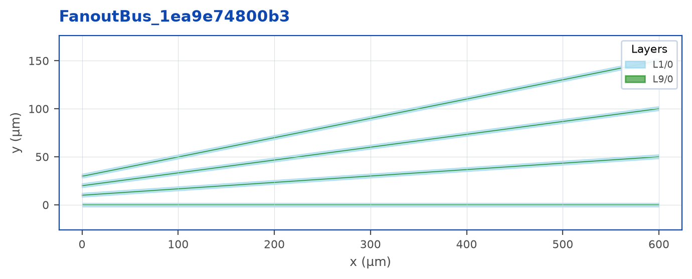
Why this matters: when you connect a 10 µm-pitched modulator array to a 127 µm-pitched fiber array, the channel-by-channel fanout you’d write by hand is identical for every chip you ever build. Route does it once, correctly, with bend-radius-aware staircase math.
For tighter pitches where the staircase math wastes space, pass fanout="sbend" for a curved fanout instead.