Routing
Routing connects two ports with a waveguide. The auto-router handles the common cases; manual .go() chains let you take control where you need to.
Auto-routing
The simplest call:
"""Ports and your first route.

A port is a named connection point on a cell. The auto-router can
connect any two ports — it picks Manhattan or curved geometry based on
the port directions, with bend radius drawn from the route layer's
design rules.
"""
import lumicron as lm
import lumicron.pdks.elyon_demo.all as pdk


@lm.pcell
def PortsAndRoute():
    c = lm.CELL("PortsAndRoute")

    c.add(lm.PORT(
        "in", position=(0, 0), direction=0,
        width=0.5, layer=pdk.LAYER.SILC,
    ))
    c.add(lm.PORT(
        "out", position=(400, 200), direction=180,
        width=0.5, layer=pdk.LAYER.SILC,
    ))

    c.Route(c.ports["in"], radius=10).to(c.ports["out"])
    return c


if __name__ == "__main__":
    PortsAndRoute().to_gds("ports_and_route.gds")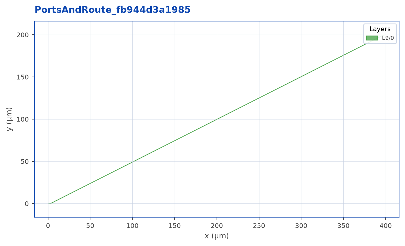
Route(a, radius=10).to(b) picks geometry based on port directions:
| Port pair | Geometry |
|---|---|
| Cardinal, perpendicular | Manhattan elbows |
| Cardinal, parallel + offset | Direct (Dubins arcs) |
| Any non-cardinal port | Direct |
Force a specific style with style=:
"""Three ways the auto-router can connect two ports.

`Route(a, b)` picks geometry based on port directions:
    - cardinal + perpendicular → Manhattan (90° elbows)
    - cardinal + parallel       → direct (Dubins arcs)
    - any non-cardinal          → direct
You can force a style with `style="manhattan" | "direct" | "sbend"`.
"""
import lumicron as lm
import lumicron.pdks.elyon_demo.all as pdk


@lm.pcell
def RouteStyles():
    c = lm.CELL("RouteStyles")

    # Three port pairs stacked vertically. Same span, different styles.
    rows = [
        ("manhattan", 0, 200),
        ("direct", 0, 600),
        ("sbend", 0, 1000),
    ]
    for style, y, _ in rows:
        c.add(lm.PORT(
            f"{style}_in", position=(0, y), direction=0,
            width=0.5, layer=pdk.LAYER.SILC,
        ))
        c.add(lm.PORT(
            f"{style}_out", position=(400, y + 80), direction=180,
            width=0.5, layer=pdk.LAYER.SILC,
        ))
        c.Route(
            c.ports[f"{style}_in"],
            radius=20,
            style=style,
        ).to(c.ports[f"{style}_out"])
    return c


if __name__ == "__main__":
    RouteStyles().to_gds("route_styles.gds")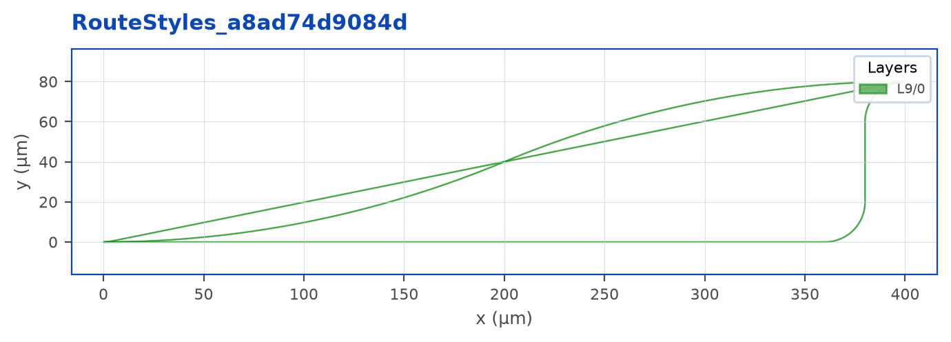
Note
radius sets the analytic bend layout footprint in µm. The required minimum curvature radius is checked on rendered geometry; Euler footprint and minimum curvature differ. Invalid geometry can fail during finalization. For straight-only routes (cardinal, no offset), pass radius=0.
Bends
Bend type is set on the Route(...) call:
chip.Route(a, radius=10, bend="circular").to(b)  # constant-radius arc (default)
chip.Route(a, radius=10, bend="euler").to(b)     # clothoid - zero curvature at entry/exit
chip.Route(a, radius=10, bend="euler", p=0.5).to(b)
chip.Route(a, radius=10, bend=my_pcell).to(b)    # custom 90° PCell
The p parameter controls the Euler contribution. p=0 is circular and p=0.5 is fully Euler. The declared layout radius is not necessarily the minimum curvature radius; minimum-radius rules apply to the rendered curvature.
A custom bend is just a CELL with i1 and o1 ports - see the section-transitions example in Chapter 5.
Manual routing with .go() and .jog()
When you need a specific shape, take over with .go():
"""Manual routing with .go() and .jog().

Sometimes you want explicit GPS-style turn-by-turn instructions:
    - .go(direction, by=...) advances the route by that amount.
    - .go(direction, to=...) advances until reaching that coordinate.
    - .jog(direction, by=...) inserts a U-shaped detour offset.
Use cases: delay lines, MZI arms, anywhere you need a precise shape.
"""
import lumicron as lm
import lumicron.pdks.elyon_demo.all as pdk


@lm.pcell
def ManualRouting():
    c = lm.CELL("ManualRouting")

    c.add(lm.PORT("in", position=(0, 0), direction=0,
                  width=0.5, layer=pdk.LAYER.SILC))
    c.add(lm.PORT("out", position=(800, 300), direction=180,
                  width=0.5, layer=pdk.LAYER.SILC))

    # Manual chain: east 200, north 300, east to port_b, then auto-finish.
    (c.Route(c.ports["in"], radius=15).to(c.ports["out"])
        .go("E", by=200)
        .go("N", by=300)
        .go("E", to=c.ports["out"].position[0] - 50))
    return c


if __name__ == "__main__":
    ManualRouting().to_gds("manual_routing.gds")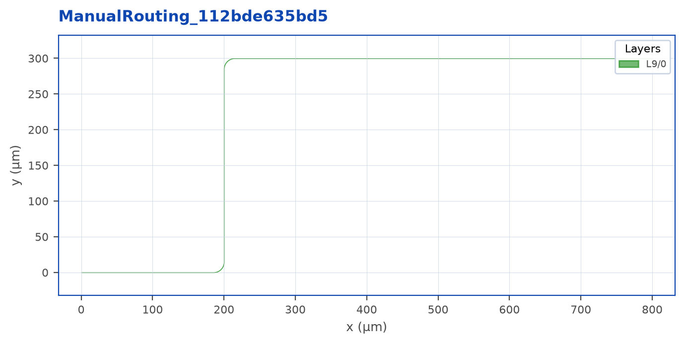
.go(direction, by=...)advances the unrounded waypoint by that many µm. A bend trims the adjoining straight: a north waypoint 50 µm away with a 5 µm circular corner leaves 45 µm of vertical straight. The waypoint displacement is not a requested straight length..go(direction, to=...)advances until the named coordinate..go("NE" / "NW" / "SE" / "SW", by=(dx, dy))lays an S-bend in that diagonal..jog(direction, by=...)inserts a U-shaped detour shifting the route byby. Useful for delay lines and MZI arms.
After your last .go(), the route auto-finishes to port_b if not already aligned.
Routing bundles
To route many parallel channels with a single call:
"""Route — route N parallel channels with one call.

Three modes, picked by what you pass:

    - `Route(...)` (default style)            → direct: per-channel,
                                                       no coordination.
    - `Route(..., style="manhattan")`         → auto-spined manhattan
                                                       bundle; the router
                                                       picks the shortest
                                                       path from ports_a's
                                                       centroid to ports_b's.
    - `Route(...).go("E", by=...)`            → manhattan-spined too,
                                                       but you steer the
                                                       spine leg by leg.

This example uses the auto-spined form, which is the right default when
your bundle just needs to "go from A to B."
"""
import lumicron as lm
import lumicron.pdks.elyon_demo.all as pdk


@lm.pcell
def BundleDemo(n: int = 4, pitch: float = 40.0, span: float = 600.0,
               y_shift: float = 200.0):
    c = lm.CELL("BundleDemo")

    for i in range(n):
        y = i * pitch
        c.add(lm.PORT(
            f"in{i}", position=(0, y), direction=0,
            route_profile=pdk.RP.silc_strip,
        ))
        c.add(lm.PORT(
            f"out{i}", position=(span, y + y_shift), direction=180,
            route_profile=pdk.RP.silc_strip,
        ))

    ports_a = [c.ports[f"in{i}"] for i in range(n)]
    ports_b = [c.ports[f"out{i}"] for i in range(n)]
    c.Route(ports_a, spacing=pitch, radius=15,
                  style="manhattan").to(ports_b)
    return c


if __name__ == "__main__":
    BundleDemo().to_gds("bundle_demo.gds")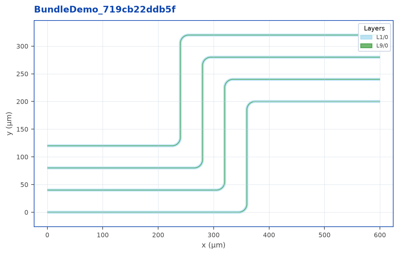
Route(ports_a, spacing=10, radius=15).to(ports_b) returns a chain that broadcasts to every channel. There are three modes:
- Direct mode (default - no
style=,.go()or.jog()): each pair routes independently. The bundle is a convenience grouping; channels don’t coordinate. Use this when ports are already aligned and you just want a vectorizedRoute(). - Manhattan-spine, auto (
style="manhattan", no.go()or.jog()): the bundle auto-computes a shortest-path manhattan spine fromports_a’s centroid toports_b’s centroid - 1, 2, or 3 legs depending on the geometry. Channels share the spine, fanouts absorb pitch differences at each end, and the bundle’sspacing=is honored everywhere. This is the right call for almost every “I want N parallel waveguides on a fixed pitch” scenario. - Manhattan-spine, manual (
.go(...)or.jog(...)): drive the spine yourself, leg by leg. Use this when the auto-spine would clip an obstacle or you need a non-shortest route.
Access individual channels through bundle.routes, for example bundle.routes[0]. The bundle itself is not iterable or indexable. Use .taper(...) to broadcast tapers. For a bundle that has not been steered with .go() or .jog(), .match_lengths(...) rebuilds every channel as an independent trombone (see Bundle PLM below). Exact length matching on a manually steered shared spine is unsupported and raises an error.
Watch out
A manhattan bundle’s spine has minimum-leg-length constraints set by the bundle’s width ((n_channels − 1) · spacing) and bend radius. If ports_a / ports_b aren’t far enough apart to fit those staircase corners, you’ll get an explicit error telling you the geometry is too tight. Either widen the perpendicular gap, reduce spacing, reduce radius, or use direct mode if collisions are acceptable.
Length matching
Two parallel routes don’t have the same physical length unless you ask. .match_length_to(other) adds a single U-meander to the shorter route so its total length equals the longer one:
"""Length matching — equalize optical path lengths across channels.

Two arms with different physical paths. `match_length_to(other)` adds a
single U-meander to the shorter arm so its total length equals the
longer arm's length. Critical for MZI arms, parallel fiber arrays, and
any interferometer-style geometry.
"""
import lumicron as lm
import lumicron.pdks.elyon_demo.all as pdk


@lm.pcell
def LengthMatch(pitch: float = 50.0):
    c = lm.CELL("LengthMatch")

    for i in range(2):
        y = i * pitch
        c.add(lm.PORT(f"a{i}", position=(0, y), direction=0,
                      route_profile=pdk.RP.silc_strip))
        c.add(lm.PORT(f"b{i}", position=(800, y), direction=180,
                      route_profile=pdk.RP.silc_strip))

    # Bottom arm jogs south then back — makes it the longer reference.
    bot = (c.Route(c.ports["a0"], radius=15).to(c.ports["b0"])
           .jog("S", by=80))

    # Top arm: straight, then matches bot's length with an auto U-bend.
    (c.Route(c.ports["a1"], radius=15).to(c.ports["b1"])
        .match_length_to(bot))
    return c


if __name__ == "__main__":
    LengthMatch().to_gds("length_match.gds")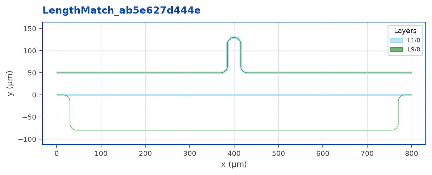
For an individual route, optional controls include:
delta=- extra ΔL to add on top of the match (e.g. for a deliberate phase offset).at=- where along the route to insert the meander (cumulative distance fromport_a).span=,amplitude=,side=- pin the meander’s footprint instead of letting the matcher choose.
bundle.match_lengths() accepts only target, delta, mirror, and tolerance; individual-route footprint controls do not apply to bundles. target_length= on Route is a positive physical path-length target.
Bundle PLM - rectangular detour
When you call .match_lengths() on a bundle that hasn’t been steered with .go() or .jog(), every channel is rebuilt as an independent rectangular detour:
port_a ─l1─┐
           │ dL
           └─l3─┐
                │ dLb
                └─l2─ port_b
Each channel’s two perpendicular leg lengths (dL_k, dLb_k) are solved analytically so the total path length ends up identical across the bundle (plus an optional per-channel delta= offset). The math is closed-form: two equations in two unknowns per channel, no iteration. Channels with different forward distances (Lx_k) are supported - a fan-out from a fiber array on one side to spread-out ports on the chip face still equalizes correctly.
chip.Route(ports_a, ports_b, spacing=10, radius=15) \
    .match_lengths()
Each channel’s detour verticals occupy a unique main-axis position (the algorithm packs them in monotonic order by sort index), so legs from different channels never share a column.
Routing direction is auto-detected from the first two ports_a positions: if they share an x, the bundle is a vertical column and routes go horizontally; if they share a y, horizontal row and routes go vertically. Pairs preserve the order of the supplied lists. Only sort=True requests transverse-coordinate pairing.
mirror= - flip the detour
By default the detours bulge in the +trans direction. Pass mirror=True to flip every channel to the −trans side, or pass a list[bool] to mirror per channel:
# Whole bundle bulges down instead of up
chip.Route(pa, pb, spacing=10, radius=15).match_lengths(mirror=True)

# Two channels up, two channels down - split bundle into stacks
chip.Route(pa, pb, spacing=10, radius=15) \
    .match_lengths(mirror=[False, False, True, True])
Mirroring is a pure geometric flip - channel lengths and net transverse displacements are preserved; only the bulge direction changes. Per-channel mirror is useful when obstacles split the routing into two halves. Adjacent channels going in opposite directions can collide if amplitudes are large; verify visually.
Watch out
The detour needs main-axis room for l1 + l3 + l2 - the inner straight l3 must be at least 2·R to inscribe the inner bends. If your ports are too close together for the geometry to fit, you’ll get a clear error naming the constraint. Move ports further apart or reduce radius / spacing.
Bundles steered with .go() or .jog() bypass this path. Exact length matching on their manually steered shared spine is unsupported.
Section-level overrides
A single Route can change profile, layer, bend, or width as it travels. The chain modifiers .style(), .radius(), .bend(), and .width() configure the next section, taking effect on the next .go() / .jog(). They never mutate the route’s global style - pass "default" to revert.
"""Section-level chain modifiers — Lumicron's wedge feature.

A single Route can change layer, profile, bend type, and width as it
travels. The chain modifiers `.style()`, `.radius()`, `.bend()`, and
`.width()` apply to the *next* `.go()` and persist until you change
them. Pass `"default"` to revert to the Route()-time global.

Auto layer transitions slot in PCells (e.g. SiLN ↔ SiLC bridges) at
every section boundary that crosses layers — you don't drop them in
manually.
"""
import lumicron as lm
import lumicron.pdks.elyon_demo.all as pdk


@lm.pcell
def SectionTransitions():
    c = lm.CELL("SectionTransitions")

    c.add(lm.PORT(
        "in", position=(0, 0), direction=0,
        route_profile=pdk.RP.silc_strip,
    ))
    c.add(lm.PORT(
        "out", position=(800, 400), direction=180,
        route_profile=pdk.RP.silc_strip,
    ))

    (c.Route(c.ports["in"]).to(c.ports["out"])
        # Section 1 — silicon strip (default from port_a.route_profile).
        .go("E", by=250)
        # Section 2 — switch to silicon-nitride strip.
        .style(profile=pdk.RP.siln_strip)
        .go("E", by=200)
        .go("N", by=150)
        # Section 3 — back to defaults but with a wider core.
        .style("default")
        .width(3)
        .go("N", to=c.ports["out"].position[1])
        .go("E", to=c.ports["out"].position[0]))
    return c


if __name__ == "__main__":
    SectionTransitions().to_gds("section_transitions.gds")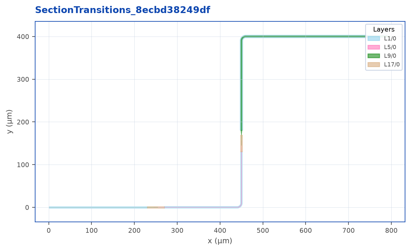
What’s happening in the example:
- Section 1 - silicon strip, inherited from
port_a.route_profile. .style(profile=pdk.RP.siln_strip)- section 2 is silicon nitride, with an automatic layer-transition PCell at the boundary..style("default")- revert profile/layer/bend..width(3)- section 3 is back on silicon, but with a 3 µm core. The router auto-inserts a linear taper at the boundary.
Tip
This is the feature most users miss for longest. If you find yourself emitting two separate Route() calls and stitching them by hand to change layer mid-route, you want section-level transitions.
.style() is the umbrella - it accepts any subset of profile=, layer=, radius=, width=, bend= plus a positional argument that auto-dispatches by type:
.style(arg) |
Effect |
|---|---|
.style(rp_obj) |
Switch route profile. |
.style(layer_spec) |
Switch the primary layer only. |
.style("name") |
Look "name" up in cell.styles. |
.style("default") |
Revert every slot to the Route()-time global. |
.radius(r), .bend(b), .width(w) are sugar for the corresponding style(...) kwargs when you only need one knob.
Tapers
Tapers come in two forms - port-end and chained - and three placements:
chip.Route(a, b, radius=10) \
    .start_taper(width=2, length=10)              # at port_a
    .taper(offset=150, width=1, length=5)         # mid-route, 150 µm in
    .taper(offset=200, width=2, length=10)        # mid-route, 200 µm after that
.end_taper(width=1, length=10) # at port_bstart_taper/end_taperconfigure the port-end transitions explicitly..taper(offset=, width=, length=)inserts a positional taper.offsetis measured from the end of the previous chain step (a.go,.jog, prior.taper, orport_a).
Width changes carry forward - the running body width after each taper is the taper’s target. If your final width doesn’t match port_b.width, the router auto-inserts a bridge taper at port_b and warns.
Layout-aware routing
clearance requests clearance around placed-cell bounding boxes for supported Manhattan routing. It is not a foundry DRC certificate or a general obstacle solver for every route style. Inspect the result and run the relevant checks for the actual PDK.
chip.Route(a, b, radius=10, style="manhattan", clearance=5)Endpoint straights and loopbacks
start_straight and end_straight are minimum physical straight lengths in micrometres, measured between the port and the bend tangent, excluding the bend footprint. They apply to auto-routing, not to explicit .go() waypoints. A shared U-turn may lengthen one side to satisfy the other side’s constraint or the port geometry. They do not set the total route length.
For two parallel, same-facing grating-coupler ports, a loopback can usually be expressed as:
c.Route(couplers.ports["GC0"], couplers.ports["GC1"],
        start_straight=50.0, end_straight=50.0)
The port route profile supplies the cross-section and default bend. Use .go() only when you need to specify the intervening path. For a parameterized loopback, place these lines inside an @lm.pcell factory and pass its length parameter to the endpoint straight settings. A PDK custom bend can have an arbitrary shape; do not infer circular length from its footprint.
Endpoint requests and compatibility
request = c.Route(a, radius=10)   # no geometry yet
route = request.to(b)             # RouteChain
route.width(1.0).go("E", by=60)   # existing section modifiers
Use Route(source, options...).to(destination) for new scripts. The two-endpoint Route(a, b, options...) remains supported. Source/destination may both be individual ports or nonempty equal-length lists/tuples. Mixed scalar/collection calls are rejected. A completed request returns the existing scalar or bundle chain and completes once; it does not add a new routing engine. Modifiers belong on the result after .to().
Handle-derived endpoints must belong to immediate instances in the same parent cell and are refreshed when .to() runs. Explicit standalone PORT values retain their supplied coordinates and unresolved identity; a coordinate alone never proves an instance endpoint. Use parent-cell coordinates consistently. Arrays have no connectable occurrences. After routing, moving an endpoint does not make the route a live placement constraint; regenerate/recreate the route to reflect the new geometry.
The statement that creates the request supplies route source provenance, including when .to() is on a later line. Existing source-anchor continuity rules still apply: named unambiguous statements can survive sibling insertion, while repeated/ambiguous construction sites do not gain invented durable identity. Source-file movement and arbitrary Python rewrites are outside that guarantee.
PDK width permission and transitions
A profile’s port_width is a fallback for a port whose width is omitted. The current router honors explicit endpoint widths; it does not widen two equal narrow ports to the nominal width automatically. Explicit section-width overrides can request a wider body.
PDK authors can share lpdk.RoutingPolicy(auto_taper=False) across their route profiles. The default is True, preserving generic linear tapers. If any participating profile forbids synthesis, a needed generic taper fails visibly at geometry resolution. Explicit compatible custom taper CELLs remain available through the existing .taper(..., cell=...), .start_taper(cell=...), and .end_taper(cell=...) options. They must declare exactly two physical ports with matching widths, layer, type, facing directions and requested straight span. Their origin is arbitrary; Lumicron aligns their ports and does not resize their geometry. Use matching widths or a PDK-provided transition when taper synthesis is forbidden. A supplied custom device is not fabrication qualification.
Finite positive widths/lengths are required. Endpoint length=0/disabled=True retains its explicit suppression behavior; it is not proof of physical width matching. Required endpoint/section tapers must fit their straight span, rather than silently disappearing. Positional tapers that overlap a bend retain the existing warning-and-skip contract; heed that warning. Multi-stroke profile taper changes retain the existing sibling-stroke warning and do not certify cladding transitions.
Distinct same-layer endpoint profile definitions are rejected: the layer-pair transition registry cannot establish strip-to-slot or other same-layer cross-section changes. Place a declared transition CELL explicitly and route to its separate ports. For different layers, the existing TransitionRegistry can supply a factory with i1/o1 ports on the declared layers; automatic placement uses transition_offset. Nothing chooses a generic elevator without that declaration. Cross-layer routing returns the downstream sub-chain; the logical route group also owns the upstream geometry and transition. A fixed target_length across that transition remains unsupported.
Inspecting and completing routes
RouteChain.length and c.inspect() resolve private snapshots. They report established centerline length, including supported taper/bend decomposition, rather than a polygon-perimeter estimate. This can be expensive and can raise an unresolved routing error. GDS-backed custom bends without explicit centerline evidence do not gain an invented length. inspect(as_dict=True) retains coverage/method information; user metadata is not a measured simulation result.
Scalar modifiers remain style, port_directions, radius, bend, width, match_length_to, taper, start_taper, end_taper, go, and jog; name is a writable label, length a read, and rules() prints guidance. Bundle modifiers remain width, radius, bend, style, port_directions, taper, match_length_to, match_lengths, finalize, go, and jog, with channels in routes. Their complete signatures are in the generated reference.
Pending style/width/radius/bend overrides are section state, not a global transformation of already committed geometry. A subsequent go/jog commits them; a trailing concrete override reconciles the final section. Repeating a pending value replaces it; "default" restores the Route-time setting where accepted. taper(offset=...) is measured from the last committed cursor, so chain order is meaningful. A scalar go with both by and to retains legacy by precedence; the bundle rejects that combination. Prefer supplying exactly one. Bundle manual steering still disables exact length matching.
Malformed manual steering/style calls restore their pending authoring state. Failed route creation restores newly added route/dependency/provenance records. Final geometry resolution uses an independent snapshot: a late failure does not finalize partial taper/bend geometry into the live authoring cell. An error does not mean a physically impossible request became valid; correct its constraints before export.